|
 |
The intent of this design was to produce a stand-alone timer that didn't depend on a computer or video camera
to make consistent and accurate measurements of the burn times of a uniform train of black powder. A human
being with a stop-watch meets the goal of stand-alone functionality, but consistency and accuracy is low
because of reaction times of the nervous system. Therefore, I designed a simple circuit to control the contacts
of a stop-watch start/stop button. Probably the biggest challenge of this approach is to find points on the
circuit board in a common digital stop-watch from which to connect control wires . The picture shows a
bottom-of-the-line stop-watch purchased from MVP for $5 US. The metal traces that connect to the switch are
very small, but quite accessible. A steady hand and a fine point soldering tool are required to attach wires to
these points so they can be controlled externally by a controller circuit. This stop-watch would have served
the purpose very well, but I eventually opted for a $20 digital stop-watch because I liked the very large
numbers it had in the liquid crystal display.
|
The schematic of the
controller circuit
will be briefly described here. All of the parts were purchased from Radio Shack or BG Micro for less than
$18 total. The circuit uses two micros-witches to sense the start and stop times of the burning train of black
powder. The switches are held with the "normally open" terminal connected to the "common" terminal by a
single thread which is positioned across the powder train. When the burning powder severs the thread, the
micro-switch delivers a change of state through a CMOS debounce latch to one of the inputs of a one-shot circuit.
Since the 74HC123 is a dual one-shot device, one of them is used to detect the start time and the other is used
to detect the stop time. Both of these events cause a one-shot to put out a 1/10 of a second pulse to a DIP relay
which closes the contacts of the stop watch start/stop button. It's a very simple circuit that is relatively easy
to build.
|
 |
This picture shows the circuit board mounted in the enclosure box . A Radio Shack (cat. no. 276-170) proto board
and project box (cat. no. 270-1808) were used at a cost of about $6 US for both. A battery pack with four AA batteries
is mounted on the outside of the enclosure for easy access.
|
 |
This shot shows the enclosure box with the lid in place. The battery pack and large display, digital stop-watch
are shown mounted on the top of the box. An on/off switch is mounted at the end of the box beside the battery
pack.
|
 |
A 4 foot length of 1 inch X 1/8 inch angle is used for containing the powder train. This is mounted on a long
wooden platform made from lengths of 1 X 4. Wood mounting brackets have been made with notches in them
to cradle the piece of angle iron. The angle merely rests on the bracket, but is not securely attached. This
facilitates easy removal of the angle for cleaning between burn tests.
|
 |
This is a close up of the place where the start thread is secured across the angle iron. For illustrative
purposes, a large, white string has been used so that the placement of the thread is clearly visible. A
common clothes pin secures the thread at both ends and eliminates the need to tie any knots. In actual use,
a very fine, artificial fiber thread, such as fuzzy nylon, is used because it melts very quickly upon contact
with the black powder flame front. A groove has been cut in the angle iron so that the thread is suspended
very close to the powder train. The start thread is positioned 6 inches from the end of the angle so that the
train of powder can extend beyond the start thread by about 4 inches. This gives the flame front propagation
a chance to stabilize before timing of its speed begins.
|
 |
The stop thread can be secured by an identical arrangement at either 45 cm or 100 cm from the start thread.
The wood block which holds the stop micro-switch can easily be moved by removing the two screws which
secure it to the platform. This angle shows that the micro-switch has a small restraining block glued to it
which limits the travel of the switch actuator. This shortens the time for the switch to register the change
in state when the thread has been severed by the flame front.
|
 |
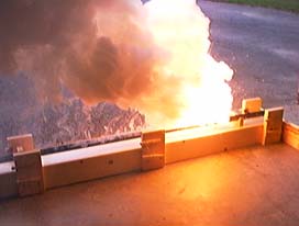
A small bolt has been installed at the start end to help secure a piece of visco under it. The visco gives
the operator a chance to retire a few feet before the powder train flares.
|
 |
This is the complete unit from a distance. Data gathered from using it to test various aspects of the black
powder manufacturing process and the effect of different kinds of charcoals will be posted below as it is taken.
If there is sufficient interest in the timer circuit, it may be worth the effort to draft up a circuit board that
would greatly reduce the effort to construct it. If you have an interest in obtaining one of these circuit boards,
let me know.
|
|
|